
Design for manufacturing in injection molding comes down to one idea: the part has to fill, cool and leave the mold the same way every shot. A DFM review is the molder reading your 3D file with that in mind, before anyone cuts steel. Every change is cheap on a CAD model and slow and expensive in hardened steel.
Here are the eight checks a DFM review runs and what to do about each. The numbers are common starting points from general injection molding design guidelines, not rules. The resin and the part decide the rest.
Checks 1 and 2: uniform walls and generous radii
Wall thickness is the first thing a molder looks at, because most molding defects trace back to it. Plastic shrinks as it cools, and thick sections cool last. When a thick area sits behind a thin surface, it keeps shrinking after the surface has set and pulls it inward — that is a sink mark. When one side of a part shrinks differently from the other, the part bows — that is warp. And the thickest section sets the cooling time, and so the cycle, for the whole part.
The fix is to keep the nominal wall as uniform as the design allows and to core out thick areas instead of leaving solid blocks. Where the wall has to change, transition gradually. A taper over a length of about three times the change in thickness is a common guideline; an abrupt step is the worst option.
Sharp corners are the second check. They concentrate stress in the part and in the steel that forms them. A common guideline is an inside radius of at least half the wall thickness, with the outside radius equal to the inside radius plus the wall, so thickness stays constant around the bend. Takeaway: if the part has one thick feature, ask whether it can be cored out before you ask about cycle time.
Checks 3 and 4: draft, then ribs and bosses
Draft is the taper on faces that run parallel to the direction the mold opens. Without it, the part drags on the steel as it ejects, which scuffs the surface, leaves heavy ejector pin marks, or holds the part in the cavity. One to two degrees per side is a common starting point for smooth faces. Zero draft is a request the molder will push back on.
Texture needs more. The peaks of a texture behave like tiny undercuts, and a frequently cited rule of thumb is roughly one extra degree per side for every thousandth of an inch (about 0.025 mm) of texture depth. The texture supplier’s specification for the pattern governs, so get it before you finalize draft on any textured face.
Ribs and bosses add stiffness and fastening points without thickening the wall, but they create their own thick spots where they meet it. The usual guidance:
- Rib thickness around half to two-thirds of the adjoining wall, so the base doesn’t sink on the show side
- Rib height up to about three times the wall; taller ribs are hard to fill and vent
- Rib spacing of at least about twice the wall, so the steel between ribs can be cooled
- Bosses cored out, with a boss wall similar to a rib, tied to nearby walls with ribs or gussets instead of standing alone
- Draft on ribs and bosses too — they are deep, narrow features and they grip the steel
Check 5: undercuts and what they cost in the tool
An undercut is any feature that stops the part from coming straight out along the opening direction: a side hole, a snap hook, an external thread, a groove. The mold can make them, but only with moving steel. Side actions (slides) pull outward before the part ejects. Lifters travel at an angle as the part is pushed off. Collapsible or unscrewing cores handle internal threads. Each one adds steel, machining, fitting and maintenance, and some add cycle time.
Often the undercut can be designed out. A snap hook can be formed through a pass-through window in the wall below it, so the tool shuts off steel against steel instead of needing a lifter. A shallow undercut in a flexible resin can sometimes be stripped off the core. When none of that works, the action is a fair cost — decide it deliberately rather than discover it in the tool quote.
Checks 6 and 7: gate, weld lines and the parting line
The gate is where plastic enters the cavity, and its position decides how the part fills. The usual guidance is to gate into the thickest section, so material flows from thick to thin and the thick area can still be packed while it shrinks. Gate type decides the mark it leaves: edge gates leave a trimmed vestige, submarine gates shear off on ejection, hot tips leave a small spot.
Wherever two flow fronts meet — around a hole or pin, or between two gates — they form a weld line, also called a knit line. It can show as a hairline and it is usually weaker than the material around it. The review moves the gate, or adds venting or an overflow, so weld lines land away from load-bearing features and cosmetic faces. On anything beyond a simple part, mold-flow simulation is the tool for this.
The parting line is where the two halves of the mold meet. It leaves a witness line on the part, it is where flash starts as a tool wears, and it sets the draft direction for every face. Mark the cosmetic surfaces on the drawing explicitly, so the parting line, the gate and the ejector pins all end up on faces nobody sees. Takeaway: a drawing that says which surfaces are cosmetic saves a full round of revisions.
Check 8: tolerances, shrink and the resin behind them
Every resin shrinks as it cools, and the cavity is cut oversize by that resin’s shrink rate. Amorphous resins such as ABS and polycarbonate shrink less and more evenly. Semi-crystalline resins such as polypropylene, nylon and acetal shrink more, and they — like glass-filled grades — shrink differently along the flow than across it, which is where much warp comes from. That is why the resin, down to the grade, should be settled before steel is cut. A tool sized for one shrink rate will not hold size in another.
Not every dimension deserves a tight tolerance. The review asks you to name the critical-to-function dimensions — fits, sealing faces, datum features, anything that mates with another part — and let everything else carry general molding tolerances. Tight tolerances across the parting line, or on features formed by a moving slide, are harder to hold because more than one piece of steel sets them.
Critical features are usually cut steel-safe: the first cut leaves extra steel where the dimension can be adjusted by removing metal after first-article measurement, because taking steel away is far easier than adding it back. And if the part will be plated or metallized, the resin needs to be a platable grade.
Every USMEX program starts with a manufacturability review
At our plant in Tijuana, every program starts with an NDA and a manufacturability review covering resin, gate and cooling, cycle and the quality plan, before anyone talks about piece price. First articles are inspected, and in-process QC runs to your quality plan.
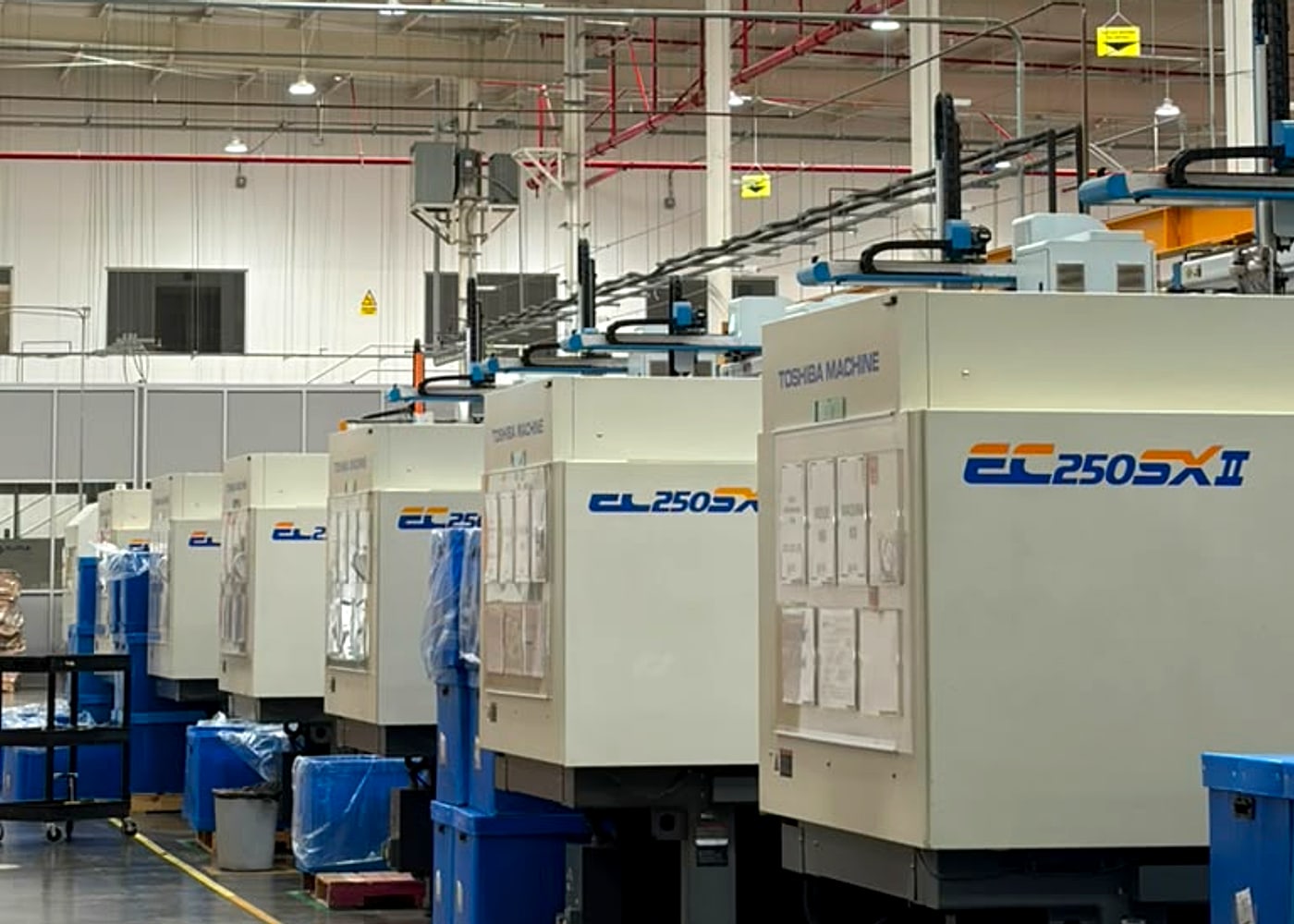
We run ten 250-tonne injection presses — seven all-electric Toshibas and three Haitian hydraulics — with a machine shop on site, so a steel-safe adjustment after first articles is made in-house and the tool doesn’t cross the border for it. If you have drawings or a 3D file, send them under NDA and we will tell you what we would change, and why.
Quick answers
What is DFM in injection molding?
Design for manufacturing is a review of the part design against how it will actually be molded: wall thickness, draft, ribs and bosses, radii, undercuts, gate and weld lines, parting line, and tolerances. The goal is a part that fills, cools and ejects the same way every shot, with as little moving steel in the tool as possible.
How much draft does an injection molded part need?
One to two degrees per side is a common starting point for smooth faces. Textured faces need more, and the texture supplier’s specification for the pattern and depth should set the final number.
When should a DFM review happen?
Before the tool is designed, and ideally before the part design is frozen. Changes are cheap on a CAD file and slow and expensive once steel is cut.
Are undercuts always a problem in injection molding design?
No. Slides, lifters and special cores handle them, but each adds cost and maintenance to the tool. Often a small design change — a pass-through window, or a feature moved to the parting line — removes the need.
What should I send for a DFM review?
A 3D file, the 2D drawing with critical dimensions and cosmetic surfaces marked, the resin (or the performance requirements if the resin is still open), and expected annual volume. An NDA normally comes first.